Vibration Sensor
Finally, and after many attempts to get some results, I got a nice graph on my computer coming from a small vibration sensor that I bout from ebay. It was a big challenge for me (and there are more challenges to come); since that it had been the first time for me to deal with USB port programming, for both Microcontroller and PC.
My aim of this project is to have a vibration data logger, along with possibility to view real time vibrations on the PC.
Best way to work with any project is to divide it into parts, the first part was to establish communication between a Micrcontroller & PC. Utilizing PIC18F4550 gave the possibility for that. Below a schematic for the circuit that I used to get this done.
 After a number of trials, I was able to get the data coming out from the chip to the PC.
The Microcontroller was programmed as HID (Human Device Interface); but still it is possible to send and receive data that way. (And no need to write a special driver for your device).
Next step was reading the data coming from the vibration sensor. At this stage I struggled a lot, geting wrong information on the PC after many trial would just get you crazy. Finally I decided to wake up, and read more. Going through some books once again, and most important thing was going through PIC18F4550 datasheet helped me to figure out where I went wrong!. (I am used to deal with PIC16F778, but configuration bits for the timer were different on PIC18F4550).
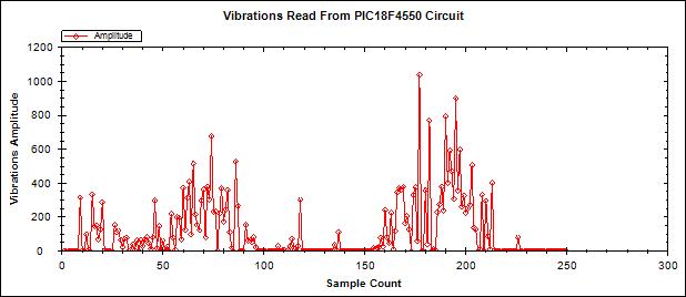
After getting my Micrcontroller fixed, finally I started getting realistic values (The more I vibrate the sensor, the higher the values I was getting. (Hurrraaaaayyyyyyy).
Below a photo for the sensor that I used for this project (The Vibration Sensor), 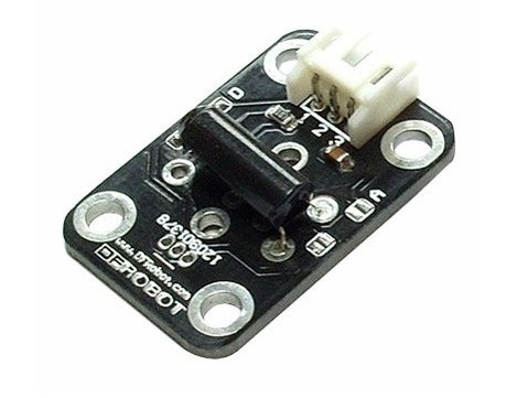 It’s really a very simple sensor, with three terminals only, Output, Vcc, and Gnd.
The only information I was able to find about this sensor is below:
* Digital input module
* Can sense the weak vibration signals
* Switch life: up to 10 million seconds
* Open circuit resistance: 10Mohm
The Digital Vibration Sensor is a digital Plug and Play sensor blocks. It can sense the weak vibration signals, which can be realized with the shock interaction with relevant works.
Product Performance:
* The conductive pin will make an instant turn-on (ON) state when touched by the outside force to achieve the proper vibration force, or an appropriate speed from the (partial) energy.
* No direction, any angle may burst.
* The switch is suitable for small-current circuit (secondary circuit) or (IC) of the trigger.
* At room temperature and normal use the next switch service life is up to 10 million times (times/1sec).
But many thanks to Mr. Sarfraz Dairkee who explained to me exactly how this sensor worked, and what kind of output would be expected from it. And he was really the main person that encouraged me to keep going with this project.
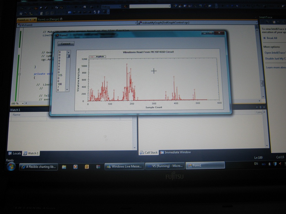
After getting realistic information, it was time to write a PC application that would plot the information. So far, I had been using a USB Terminal software used for monitoring data flow between PC and USB port.
I used my loved programming language C#.NET to write this program, and again, I started without clue on how to do that; but a lot of reading, digging, and googling always help!.
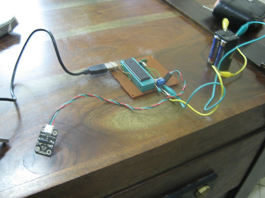
Below some photos for the circuit, and the monitoring program. As of now I am able to read proper values from the sensor, and I am able to send the information to the PC. The next step would be storing data on an SD card. This I have already started working on, but as usual, nothing is so simple. First obstacle was the 32MB SD card that I had. It turned out that it was not possible to read data to this card using PIC18F4550!. Today I am planing to get out and by a new 1GB card. More about this in Part 2.
Leave a Reply